Light development. Made simple.

From idea to the perfect light pattern.

I turn complex lighting requirements into solutions ready for series production – with light simulation in Ansys SPEOS, experience from 250+ series projects and a clear process.

★★★★★ 5.0 on Google · 250+ series projects · Certified SPEOS trainer

Fundamentals in the induux industry wiki (German): Light in the product · Light guides

Discuss your lighting issue → Read the guide
◀▶
◀ BEFORE AFTER ▶
📷 Send a photo of your light pattern →Initial assessment within 48 h, free of charge

From a non-uniform prototype to a uniform series part

Typical light defects in luminaires, light guides and control panels – and how to solve them. Installation space, optical elements, material, tolerances and manufacturing decide the light pattern. I find the cause in the light simulation, before production.

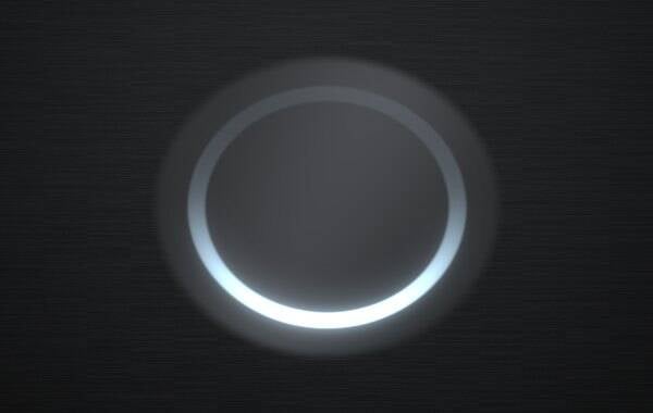
Light ring – problem: ring too dark at the top (light only arrives at the bottom)1 · Problem
Ring too dark at the topLight only arrives at the bottom
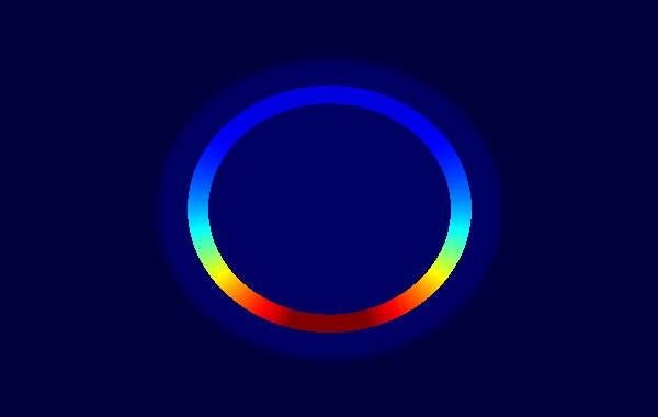
Light ring – light simulation: luminance around the ring (false colours, cd/m²)2 · Simulation
0 cd/m²max
Cause made visibleLuminance around the ring
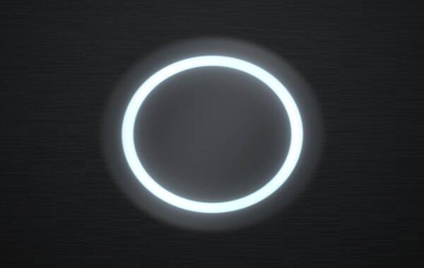
Light ring – solution: uniform ring, light guide geometry optimised3 · Solution
Uniform ringLight guide geometry optimised

Light ring – too dark at the top

The LEDs sit only at the bottom of the ring. On the way up, the light guide loses light and the ring looks one-sided. In the simulation, I see the luminance profile around the ring and adapt the geometry until it glows evenly.

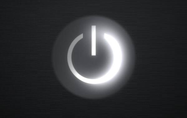
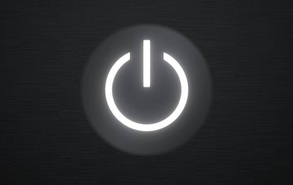
Backlit symbol – problem: light bleed and brightness drop (stray light next to the symbol)1 · Problem
Light bleed and brightness dropStray light next to the symbol
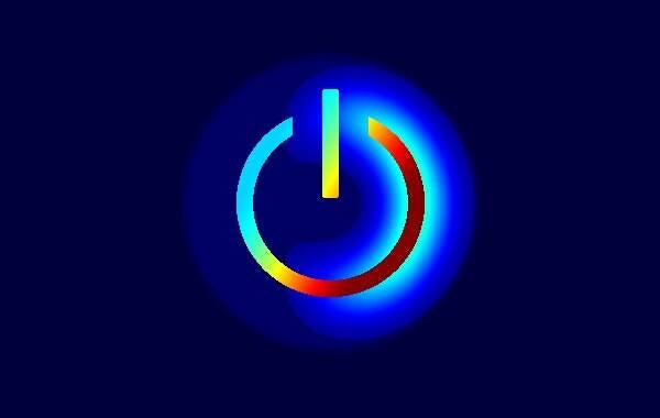
Backlit symbol – light simulation: stray light in the simulation (false colours, cd/m²)2 · Simulation
0 cd/m²max
Cause made visibleStray light in the simulation
Backlit symbol – solution: sharp, uniform symbol, shielding and diffuser adapted3 · Solution
Sharp, uniform symbolShielding and diffuser adapted

Backlit symbol – light bleed

Light escapes next to the symbol and one side is brighter than the other – typical for buttons and control panels. The simulation shows where the stray light originates. With adapted shielding and diffuser, the symbol becomes sharp and uniform.

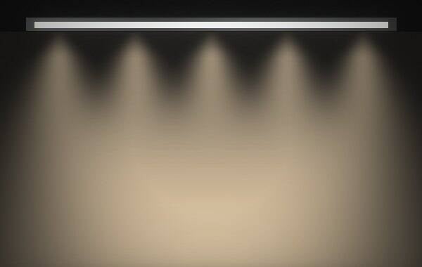
Wall washer – problem: arcs and shadows on the wall (optics spread too narrowly)1 · Problem
Arcs and shadows on the wallOptics spread too narrowly
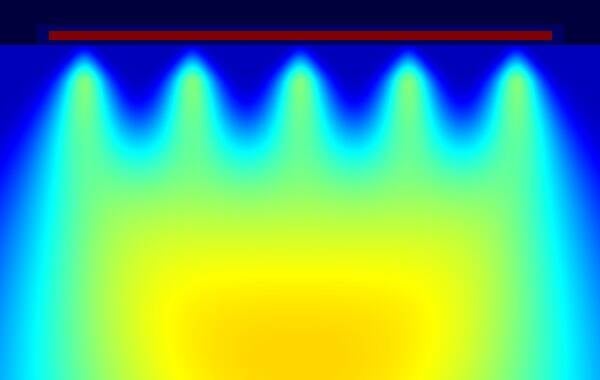
Wall washer – light simulation: illuminance on the wall (false colours, cd/m²)2 · Simulation
0 cd/m²max
Cause made visibleIlluminance on the wall
Wall washer – solution: evenly lit wall, reflector redesigned3 · Solution
Evenly lit wallReflector redesigned

Wall washer – light arcs on the wall

Instead of an evenly bright wall, the individual light cones show up as arcs. I simulate the illuminance on the wall and design reflector and optics so that the wall is lit evenly.

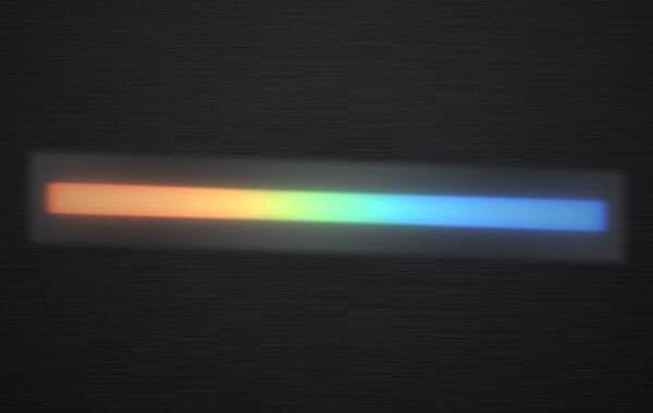
RGB light bar – problem: colour errors (LED colours visibly separated)1 · Problem
Colour errorsLED colours visibly separated
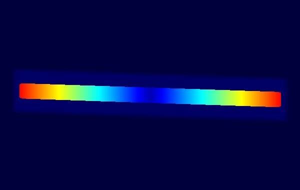
RGB light bar – light simulation: colour mixing along the bar (colour deviation)2 · Simulation
mixedColour deviation
Cause made visibleColour mixing along the bar
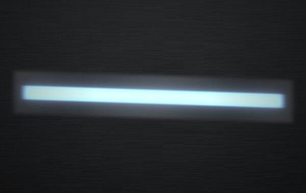
RGB light bar – solution: even mixed colour, mixing zone extended3 · Solution
Even mixed colourMixing zone extended

RGB light bar – colours don't mix

Red on the left, blue on the right instead of one consistent mixed colour. The simulation shows the colour deviation along the bar. With an extended mixing zone and an adapted structure, an even colour is created.

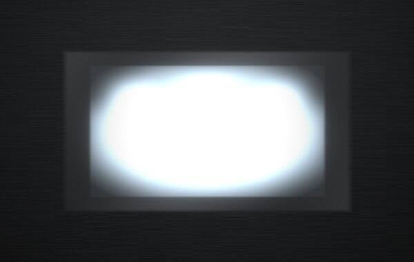
Backlit surface – problem: dark corners, bright centre (surface looks blotchy)1 · Problem
Dark corners, bright centreSurface looks blotchy
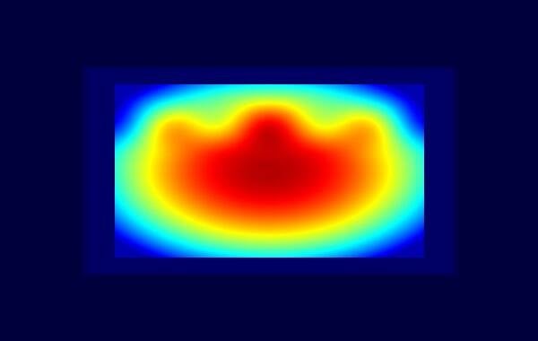
Backlit surface – light simulation: luminance across the surface (false colours, cd/m²)2 · Simulation
0 cd/m²max
Cause made visibleLuminance across the surface
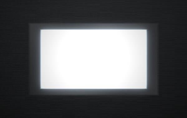
Backlit surface – solution: uniform surface, spacing and diffuser optimised3 · Solution
Uniform surfaceSpacing and diffuser optimised

Backlit surface – dark corners

The centre is bright, the corners fall off and the LED row is visible. In the luminance simulation, I optimise LED spacing, build height and diffuser until the surface glows evenly.

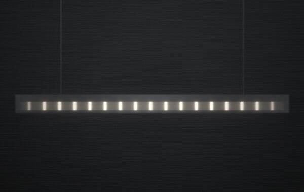
Linear luminaire – problem: string-of-pearls effect (individual LEDs visible through the cover)1 · Problem
String-of-pearls effectIndividual LEDs visible through the cover
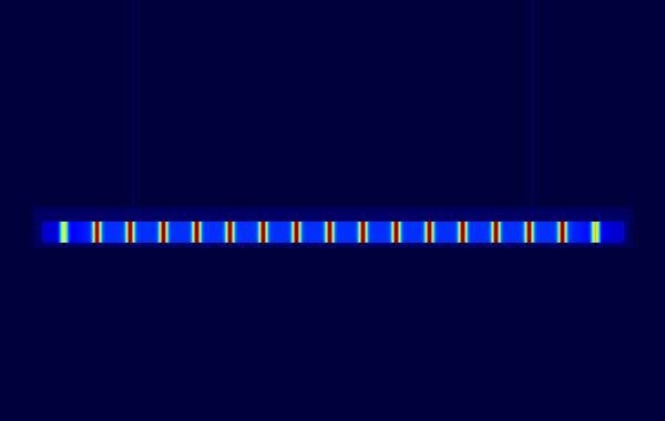
Linear luminaire – light simulation: luminance along the luminaire (false colours, cd/m²)2 · Simulation
0 cd/m²max
Cause made visibleLuminance along the luminaire
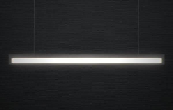
Linear luminaire – solution: continuous light line, diffuser and LED spacing designed3 · Solution
Continuous light lineDiffuser and LED spacing designed

Linear luminaire – string-of-pearls effect

Every LED is visible individually through the cover and the ends stay dark. The simulation shows the luminance profile along the luminaire. With a suitable diffuser and LED spacing, a continuous light line is created.

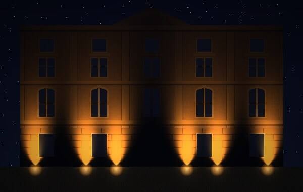
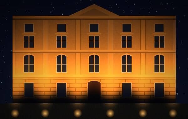
Historic façade with amber light, luminaire position A – night visualisation1 · Visualisation
Night view in amber6 ground spotlights, position A
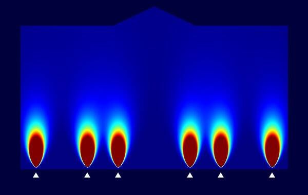
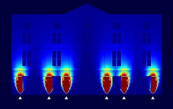
Historic façade, position A – illuminance in lux, false colours2 · Illuminance
0 lx150 lx
Lux on the façadeØ 43 lx · max 2,000 lx
Historic façade, position A – luminance in cd/m², false colours3 · Luminance
0 cd/m²20 cd/m²
Luminance in cd/m²Ø 5.2 cd/m² – this is how bright the façade appears

Historic façade – luminaires directly at the wall

Six ground spotlights directly at the wall: the light hits the façade steeply and creates bright peaks at the base of up to 2,000 lx – on average 43 lx and 5.2 cd/m². The simulation shows illuminance and luminance before a single luminaire is installed.

Historic façade with amber light, luminaire position B – night visualisation1 · Visualisation
Night view in amber6 ground spotlights, position B
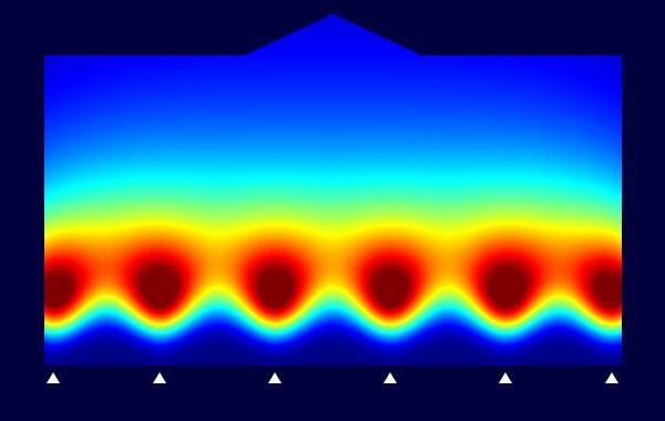
Historic façade, position B – illuminance in lux, false colours2 · Illuminance
0 lx150 lx
Lux on the façadeØ 63 lx · max 166 lx
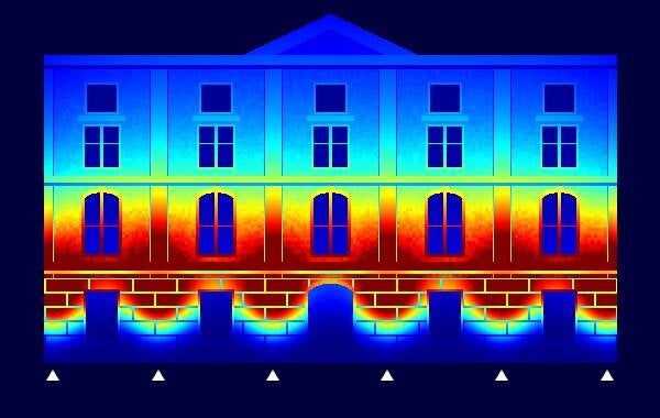
Historic façade, position B – luminance in cd/m², false colours3 · Luminance
0 cd/m²20 cd/m²
Luminance in cd/m²Ø 8.4 cd/m² – this is how bright the façade appears

Historic façade – luminaires 2 m in front of the façade

The same six ground spotlights, 2 m in front of the façade: the light spreads more evenly, without peaks (max. 166 lx) – on average 63 lx and 8.4 cd/m². The façade looks brighter and calmer. This is how position, beam angle, light colour and LED power are defined before installation.


Light simulation and development for uniformly lit products

TKLEngineering is an engineering office for light development in Langenfeld (Rhineland), Germany. Thomas Kümpfel develops light guides and light systems for automotive and industrial products and optimises the light pattern with SPEOS light simulation before the first tool is built – free of hotspots, stray light and colour errors.

250+ industrial series projects · 10+ automotive projects for German OEMs · over 95 % agreement between simulation and measurement in colour and brightness · Google rating 5.0 ★

Attractive light patterns in the end product require experience in developing uniformly lit assemblies. The combination of concept validation, series development and defect prevention ensures that every end product achieves the intended light pattern.

More under Services → Knowledge & news ›
Before/after: light guide of a status indicator with three LEDs being optimised Before/after: light path in a light guide of a status indicator with three LEDs

Frequently asked questions

What service do I get?

At the core of light development are the light simulation of your product and the creation of the data for the optical parts. On top of that, you receive in-depth product development advice on all related questions – materials, alternative concepts, installation space, suitability for series production, end-of-line testing and more.

How accurate is the light simulation?

The SPEOS light simulation is very accurate and widely used by automotive OEMs and industrial companies. Accuracy depends on the input data. When the optical data is known (materials, LED data, surfaces), simulation and later measurement on the real part agree by more than 95 % in colour and brightness.

Example from practice: a vehicle light guide was simulated at 399 cd/m² and measured at 410 cd/m² on the real part – less than 3 % deviation.

How do you find the best light pattern at the lowest cost?

Behind every light pattern is a light system consisting of LED, surrounding parts and light guide. The light systems comparison in the guide shows how to achieve the brightest and most uniform products – with comparisons of efficiency, product brightness and cost.

Can I get prototypes or only virtual development?

On request, prototypes and series parts for light guides, optics and housing parts can be supplied through a reliable partner network.

What are the benefits for my product development?

You have LEDs in your product and don't know where the ideal position is? You want your product to shine better than the competition? You need maximum brightness with ideal use of space and a uniformly lit light window at the same time? These and many other topics are part of professional light design. Together we find the right concept and give your product a high-quality appearance through individual light development – with light simulation and CAD, without building prototypes, through to light systems ready for production.

Results from real projects:

  • Stray light of a status LED reduced by 79 % (116 → 25 cd/m²)
  • Evenness of a charge indicator increased from 37 % to over 90 %
  • Vehicle light module: uniformity increased from 40 % to 87 %
  • Toy button: brightness increased from 300 to 610 cd/m²
What does TKLEngineering do?

TKLEngineering is an engineering office for light development in Langenfeld (Rhineland), Germany, run by Thomas Kümpfel. We develop LED light guides and complete light systems for automotive and industrial products – from light simulation with Ansys SPEOS through CAD design to series support.

Which typical light defects can be avoided?

Common defects are hotspots and visible LED positions, non-uniform light surfaces, light spilling into neighbouring symbols (light bleed), colour fringes with mixed colours and spots caused by holders. Light simulation shows the cause before tools are built – typical solutions are a changed LED position, optimised outcoupling structures, diffusers or a different material.

Which industries does TKLEngineering work for?

Automotive interiors (instrument panel, door trims, headrest lamp, charge level indicator, licence plate lamp) and industrial products: household appliances, controls and wall switches, bathroom fittings, wallboxes, medical devices and toys – for example the LED ring of the Toniebox 2 by tonies. In total more than 250 industrial series projects and more than 10 for German car manufacturers.

What data do you need for a light simulation?

Ideally 3D CAD data of the product (e.g. STEP), the datasheet of the LED used and details of the materials of the light and housing parts. The more accurate the optical input data, the more accurate the prediction of brightness and colour. On request, a non-disclosure agreement (NDA) can be signed beforehand.
Example videos of the simulation

Avoiding light defects: uniformity, colour mixing and light systems

Light bars in blue, red and green with visible colour errors

Uniformity

For the highest possible quality and appearance of ambient or functional lighting, light defects must be avoided. Their causes are manifold: too little development time (LED position, mountings, light system) or the subsequent implementation of the specifications in manufacturing and production.

What makes good light quality ›
Light simulation: red and green LED light mixing in a light guide

Colour mixing

Functional status lighting often uses multi-colour LEDs whose colours are switched. To save cost, red and green LEDs can also display orange: light guides transport the light from the LED and at the same time combine red and green over the path length to create orange by colour mixing.

Colour mixing with light guides ›
Illuminated on/off switch with light ring and visible LED positions

Light in the product

Behind every light pattern is a light system consisting of LED, surrounding parts and light guide. Learn how to achieve the brightest and most uniform products – comparisons, efficiency, product brightness and cost.

Light systems compared ›
Thomas Kümpfel, light development engineer
“I'll reply to you personally – within 48 hours.”

Send me a photo of your light pattern or your CAD data – you get an initial assessment, free of charge and without obligation. NDA on request.

Thomas Kümpfel · Light development engineer · Langenfeld, Germany

📷 Send a photo →

Your engineering
partner

10+years of experience
250+series projects
5.0 ★Google rating

★★★★★ “The expertise in light and optics development is remarkable. Every technical question was answered with profound knowledge.”Reinhard Neudecker · Google review (translated from German)