

Reference projects
Uniform light lines and light surfaces in a wide range of products – developed for leading German industrial companies and car manufacturers.
Industries & applications
Industry 250+
Series projects for leading German industrial companies
WallboxesBathroom fittingsControlsWall switchesCharging rampsToysMedical devicesu. v. m.Automotive 10+
Series projects for German OEMs
Instrument panelDoor trimsCharge level indicatorLicence plate lampHeadrest lampu. v. m.What goes into every project
Brightness simulation
Projects are won with reliable brightness simulations.
Light prototypes
Design, measure and evaluate prototypes.
Light guide systems
Build light guides, optimise outcoupling structures and take them into series production.
Interdisciplinary
Work with every discipline to avoid light defects.
Results in figures
Key figures from real projects.
Project stories
Projects in detail – from the first lighting concept to series production. Click a tile for the full story.
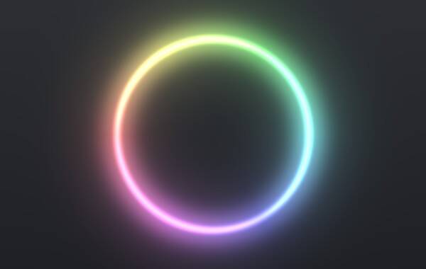 Toys · toniesLight ring of the Toniebox 2Read story ›
 AutomotiveInterior light module without blotchesRead story ›
 Building technologyStatus light without stray lightRead story ›
 AutomotiveCharge indicator: even instead of blotchyRead story ›
 AutomotiveRGB colour mixing in the light guideRead story ›
 ConsumerButton symbol twice as brightRead story ›
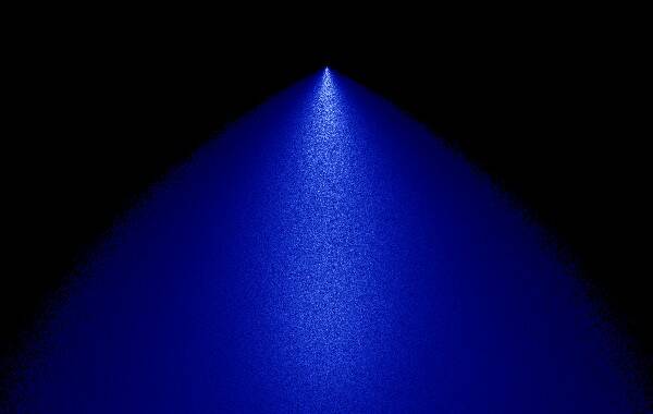 MedicalLight guide head for a dental handpieceRead story ›
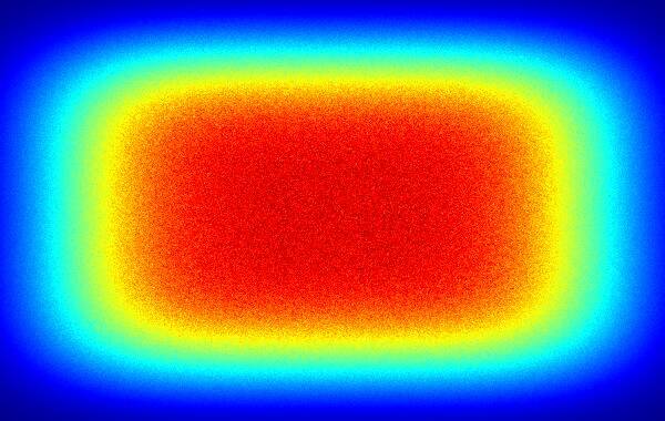 LuminairesSurface light without LED gridRead story ›
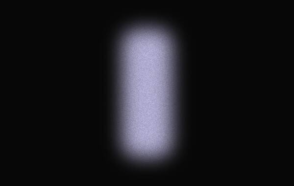 FurnitureLED strip under glass: the dots disappearRead story ›
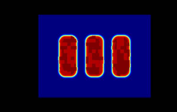 Building technologyRoom controller: corona halvedRead story ›
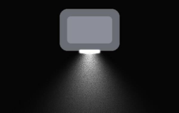 IndustryAmbient light for an enclosureRead story ›
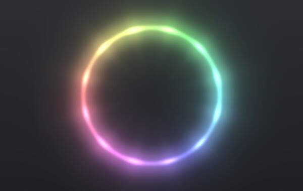
The light ring of the Toniebox 2
The Toniebox 2 works without a screen. What it is doing is shown by a glowing ring – intuitive for children, readable at a glance for parents. My task: to design this ring so that it appears as a uniform light line , mixes colours cleanly and convinces everywhere from a bright children's room to a night light.
Drag the slider: before, shadows between the LEDs (string of pearls); after, a uniform light line. (Illustration)
Starting point: light as a language
The ring is the box's central feedback. Its colour and animation show which state it is in:
Every state must be recognisable instantly – even out of the corner of the eye, even for a three-year-old.
The challenge
- Dots instead of a line: A narrow ring fed by individual LEDs – without good light guidance, every LED shows up as a bright spot.
- Colour mixing: For the rainbow and the status colours, the RGB components must arrive mixed, without colour fringes.
- Stray light: No light may escape into the housing or through gaps.
- Brightness range: Clearly visible in daylight, soft and glare-free as a night light.
- Series production: The result has to work with part and LED tolerances in high volumes.
Approach: simulate first, then build
With Ansys SPEOS, I built the ring virtually – with LED ray files, material data and the real housing geometry. This allowed variants to be evaluated before any tool existed:
- Number and position of the LEDs
- Geometry of the light guide and outcoupling structures
- Diffuser and material selection
- Shielding against stray light
Result
The light ring went into series production with the Toniebox 2 – as an evenly glowing, colour-rich status indicator.
Client testimonial from tonies coming soon.
Christian Wilmanns · VP Product Development, tonies
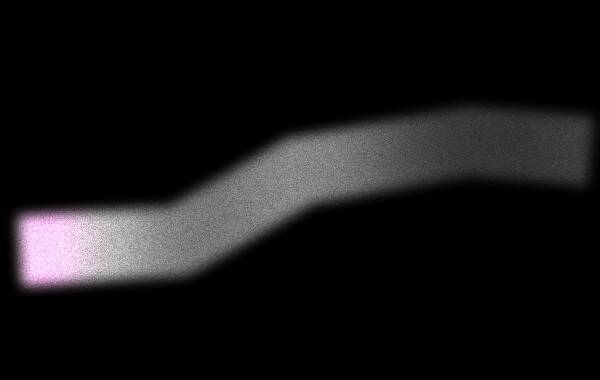
Interior light module without blotches
A light module in a vehicle interior with a shaped light lens: viewed head-on it looked fine, but in the real installed position it was blotchy – with colour fringes at the start of the light window.
Drag the slider: before and after (illustration).
Starting point
The underside of the lens had been laser-roughened to extract the light – without an additional diffuser.
The challenge
- Frontal uniformity only approx. 40 %
- Brightness ratio of 5 : 1 in the installed position
- Visible colour fringes at the start of the light window
Approach
I simulated surface roughness against volume diffusion in Ansys SPEOS – head-on and from the driver's real viewing direction.
- Laser roughness vs. volume diffuser
- Diffuser strength and material thickness
- Evaluation in the installed position, not just head-on
Result
A strong volume diffuser (1.5 mm) instead of surface roughness makes the light pattern uniform – without colour issues.
Status light without stray light
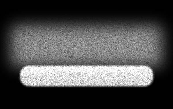
A wall switch with a backlit surface and status LED: the backlight shone into the status area – the status was barely visible in daylight.
Drag the slider: before and after (illustration).
Starting point
The status light is meant to reach 100–300 cd/m². But 116 cd/m² of stray light from the backlight was already arriving in the status area.
The challenge
- Contrast between status on and off too low
- Light travels through light guide and housing
- The solution must not darken the backlight
Approach
In the simulation, I compared eight variants – from coating to material choice in the housing.
- Black paint on the light guide
- Diffuser and surface choice in the housing
- Evaluation of the stray light luminance per variant
Result
The combination of paint and an adapted housing significantly reduces stray light – the status is clearly readable again.
Charge indicator: even instead of blotchy
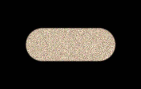
A charge indicator in a vehicle interior (RGB and white): the first data release glowed blotchy and grainy.
Drag the slider: before and after (illustration).
Starting point
Min/max luminance in the first release: 185 to 496 cd/m² – an evenness of only 37 %.
The challenge
- Visible brightness blotches
- Several colours in the same light guide
- Realistic material and surface data needed
Approach
I redesigned the inner light guide and calculated with measured material data so that the simulation matches the later part.
- Optimised inner light guide
- Measured BRDF material data
- VDI roughness of the surfaces
Result
The light pattern is even – two light reports in ten days to the solution.
RGB colour mixing in the light guide
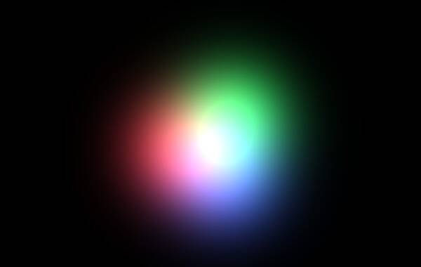
An RGB LED feeds a light guide in a vehicle interior. Without measures, red, green and blue spots were visible instead of a mixed colour.
Drag the slider: before and after (illustration).
Starting point
The three LED chips sit side by side – right behind them, the colours separate spatially.
The challenge
- Colour spots directly visible
- Little space for a mixing distance
- Efficiency must be maintained
Approach
I simulated the length and cross-section of a mixing section and evaluated the colour coordinates along the light guide.
- Mixing element with polygonal cross-section
- Length of the mixing distance
- Colour coordinate and efficiency evaluation
Result
After 20 mm the colour is well mixed locally – white light without colour fringes, with high efficiency.
Button symbol twice as bright
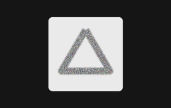
An illuminated button symbol on a consumer product: in the worst case it was hard to see in bright surroundings.
Drag the slider: before and after (illustration).
Starting point
At the lowest LED brightness (1 lm per LED), the symbol only reached approx. 300 cd/m².
The challenge
- Visibility in bright surroundings too
- Keep the symbol uniform
- No stronger LEDs wanted
Approach
I varied diffuser thickness, length and material and compared brightness and evenness each time.
- Thinner, shorter diffuser
- Alternative, lighter diffuser material
- Worst case with LED tolerances
Result
With a thinner diffuser, the symbol is twice as bright and clearly visible in daylight.
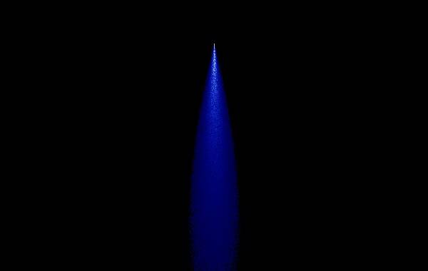
Light guide head for a dental handpiece
A dental handpiece with an interchangeable light guide head is meant to direct blue light precisely onto a surface.
Drag the slider: before and after (illustration).
Starting point
The straight head without mirror only produced a narrow spot of max. approx. 120 mW/cm² at 7 mm distance.
The challenge
- Couple light efficiently into the head
- Large, even light field
- High irradiance in a small installation space
Approach
Over several development phases, I simulated coupling, head geometry and outcoupling surface and handed them over as STEP data.
- Chrome-plated outcoupling surface
- Optimised head geometry
- Direct coupling without front lens (> 90 %)
Result
A light field of 1.5 × 3 cm instead of a narrow spot – significantly more efficient than the state of the art.
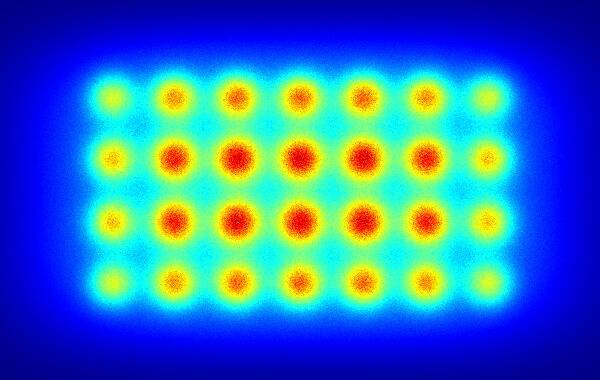
Surface light without LED grid
An LED matrix behind a diffuser plate was meant to produce a uniform luminous surface – instead, every LED was visible as a dot.
Drag the slider: before and after (illustration).
Starting point
With 60° LEDs, the LED grid showed clearly on the surface.
The challenge
- Uniform surface without dot pattern
- Installation space must not grow
- Simple solution suitable for series production
Approach
I systematically varied the distance (8, 10 and 12 cm) and beam angle of the LEDs.
- Distance LED to diffuser plate
- Beam angle 60° vs. 120°
- Evaluation in the false-colour image
Result
Switching to 120° LEDs produces a uniform surface – with the same installation space.
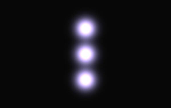
LED strip under glass: the dots disappear
An LED strip under a glass panel in a piece of furniture: the individual LEDs were visible as harsh dots.
Drag the slider: before and after (illustration).
Starting point
Luminance peaks above 150,000 cd/m² – the light was neither uniform nor pleasant.
The challenge
- Make the LED dots invisible
- Avoid glare
- Keep enough brightness
Approach
In six simulation runs, I varied the diffuser thickness and the mounting depth of the LED strip.
- Thicker diffuser (3–5 mm)
- LED strip set 5 mm deeper
- Uniform variant at approx. 300 cd/m²
Result
The LED dots are no longer visible, and the current can even be reduced.
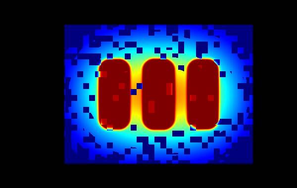
Room controller: corona halved
A room controller with backlit display fields: a stray-light corona surrounded every symbol across the whole field.
Drag the slider: before and after (illustration).
Starting point
The corona ranged from 140 to 1,400 cd/m² and covered the entire 20 × 20 mm field.
The challenge
- Symbols should look sharp
- No light in neighbouring fields
- Small parts, little leeway
Approach
I simulated and compared lens thickness, LED position and the surface of the print.
- Thinner lens
- LED offset by 1 mm
- Glossy white instead of matt print
Result
The corona is much weaker and only half the size – the display looks crisp.

Ambient light for an enclosure
An industrial enclosure was to get subtle ambient light – the first unstructured light guide was practically invisible.
Drag the slider: before and after (illustration).
Starting point
Without structures, a maximum of 1 cd/m² reached the light guide surface – imperceptible as ambient light.
The challenge
- Target: 40–100 cd/m², dimmable
- Clearly defined light pattern
- Simple to manufacture by injection moulding
Approach
I simulated six light guide variants with prisms, bevels and VDI roughness.
- Prism and bevel variants
- Bevel with VDI 21 surface
- Light pattern size and luminance evaluated
Result
With a bevel and VDI 21 surface, the ambient light is clearly visible – the target is reached reliably.
What clients say
“The expertise in light and optics development is remarkable. Every technical question was answered with profound knowledge and clearly understandable explanations. […] I can recommend this collaboration without reservation.”
Reinhard Neudecker · Google review, 5 ★ (translated from German)
Could your project be the next reference?
Send a photo of your light pattern or your CAD data – initial assessment within 48 h, confidential and without obligation.
Request a project → View services