
Light development for LED products – from idea to series production
The guide distilled from more than 250 series projects: light systems, light simulation with Ansys SPEOS, typical light defects – and how to avoid them before production.
1 · What is light development?
Light development is the systematic engineering process of integrating light into products and devices – from the first concept to a design ready for series production. It is no longer just about simple indicator lights or status displays: modern light design combines function, aesthetics and technical precision and visibly adds value to a product.
LEDs keep getting more powerful and compact – which opens up new possibilities for light in the product. Whether uniform light lines on a charging station, a colour-coded LED ring on a consumer product or subtle ambient lighting in a vehicle: professional light development decides whether a lighting concept succeeds or fails in series production.
Why light development is essential
Light sets products apart from the competition and creates recognition.
Status indicators, states and user guidance through light.
Light design creates perceived quality and strengthens brand identity.
Only a structured process ensures defect-free light patterns in series production.
Heads of development and design engineers often have to integrate light functions into existing component architectures – with limited installation space and tight cost targets. This is exactly where specialised light development comes in.
2 · The process: from idea to series production
Four phases – and what you get in each one.
Requirements
CAD design
Simulation
Series production
1 · Concept validation and requirements analysis
It starts with one question: which requirements must the light pattern meet? Luminance targets, colour temperatures, uniformity criteria and functional requirements are defined. Even at this stage, an initial light simulation can check feasibility and reveal risks – before a single CAD model exists.
2 · CAD design of the light system
- Light guide geometry: shape, cross-section, bend radii and outcoupling structures
- LED positioning: distance, angle and thermal management
- Optical elements: diffusers, reflectors and holding structures
- Component integration: design for injection moulding, tolerances and assembly context
Design work is done in common systems such as CATIA V5, NX, SolidWorks or SpaceClaim – matched to your manufacturing processes.
3 · Light simulation and optimisation
Light simulation is the heart of modern light development. It allows the light system to be evaluated and optimised virtually and significantly reduces physical prototype loops. That saves time and money and avoids expensive iterations in tool making.
4 · Series development and manufacturing advice
In the final phase, the lighting concept is secured for series production: tolerance analyses, LED bin assessments and manufacturing optimisations ensure that the light pattern stays convincing under real production conditions.
3 · Light simulation: virtual evaluation before the prototype
Ansys SPEOS has become the leading simulation tool in light development. It reproduces light transport with photometric accuracy – from the LED source through the light guide to the visible light pattern.
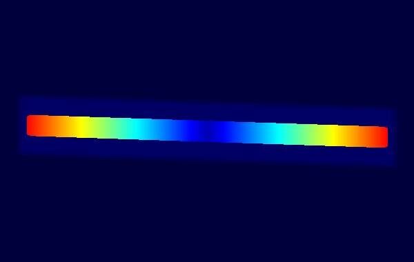
 Brightness & uniformity
 Colour
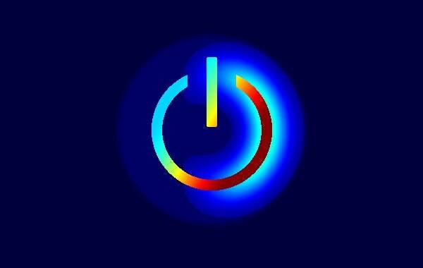 Light defects
What light simulation delivers
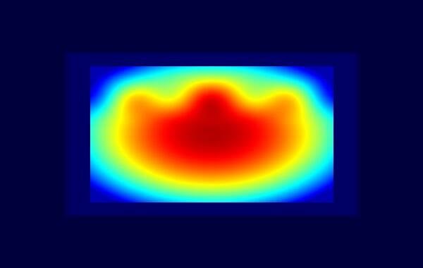
- Brightness simulation: evaluate luminance and illuminance quantitatively
- Uniformity analysis: detect spots, dark areas and irregularities
- Colour simulation: predict colour fringes, deltaE deviations and yellow tint
- Tolerance assessment: analyse the influence of LED bin spread and position tolerances
- Outcoupling structure optimisation: improve prism bands and microstructures automatically
- Defect analysis: reveal stray light, reflections and unwanted light effects
Besides SPEOS, the industry also uses LucidShape, mainly for automotive exterior lighting. Which tool fits depends on the application and the customer's software landscape.
4 · Light guides and light systems compared
Light guides carry light from the LED to the visible light window and shape the light pattern on the way. Their design largely determines the quality of the light function.
One-piece
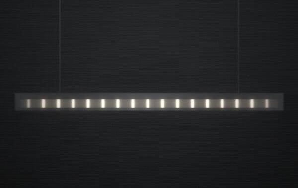
The light guide connects LED and light window directly. Advantage: little installation space, low cost. Disadvantage: on larger surfaces, exposed sections create stray light.
Two-piece
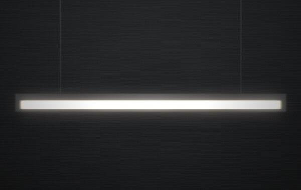
Light guide plus diffuser for larger lines and surfaces. Prism bands or microstructures direct the light out precisely. Challenge: spots and efficiency losses – optimised by simulation.
Three-piece ≈ +30 % brightness
Light guide, diffuser and white holder or reflector. The white holder increases brightness by approx. 30 % and prevents stray light – best uniformity and light quality.
Special process: 2K light guides in injection moulding
Two-component overmoulding of light guides is established but needs special attention: on the overmoulded surfaces, total internal reflection is disturbed – light is partly reflected, transmitted and absorbed. A light simulation predicts the effect on efficiency and uniformity so that the design can be adapted in time. More in the article ›
5 · Light quality and typical light defects
The quality of a light pattern is determined by four criteria. A flaw in any one of them significantly lowers the perceived product quality.
No rainbow effect, no colour fringes, no yellow tint.
No spots, no dark areas.
The light pattern stays the same from every viewing angle.
Sufficient luminance for every environment.
| Light defect | Typical cause | Solution |
|---|---|---|
| Hotspots | Insufficient diffusion or wrong outcoupling structures | Optimise the prism band distribution by simulation |
| Stray light | Exposed light guide sections without cover | Three-piece system with reflector/holder |
| Colour fringes | Mixing distance too short with multi-colour LEDs | Adapt light guide cross-section and path length |
| Yellow tint | Material absorption in long plastic light guides | Optimise the material, reduce path length |
| Brightness differences | LED bin tolerances (up to 100 % deviation) | Specify bin restrictions, validate by simulation |
| Position deviations | Assembly tolerances shift the light pattern | Tolerance analysis in SPEOS |
Consistent light simulation in every phase is the most effective way to detect light pattern defects early. More on light quality ›
6 · Ambient lighting in automotive
Ambient lighting has become a key differentiator in automotive light design: targeted light staging conveys quality, comfort and brand identity.
Indirect lighting
The predominant technique in the interior: the light system illuminates a visible surface – for example in the instrument panel or door trim – while the light source stays hidden. Result: soft, uniform light accents without glare.
Direct lighting
Visible light surfaces with a diffuser as the optical finish. The diffuser homogenises and hides the technology – known as “hidden until lit” or “shy tech”: the light function only becomes visible when switched on.
Luminance guide values (cd/m²)
0.1–10Dusk
10–50Overcast day
200–400Daylight
400–600Light sun
600–1,200Bright sun
> 3,500
An automotive light system has to cover this range of several orders of magnitude. Light simulation with SPEOS ensures visibility in all conditions. More on ambient lighting ›
7 · Colour mixing with light guides
Multi-colour LED solutions are standard. For status indicators, colours are often mixed – for example red and green to orange. Light guide cross-section and optical path length are decisive; if the mixing distance is too short, colour fringes appear.
Rule-of-thumb calculator
The light window width should not exceed the distance from LED to light window.
Minimum mixing distance: ≥ 12 mm
8 · Applications
Industrial products
- Wallboxes and e-mobility: status indicators and brand lighting
- Bathroom fittings and sanitary: temperature feedback and design lighting
- Controls and wall switches: functional lighting and orientation
- Consumer electronics: LED rings, status indicators, design accents
- Medical devices: standard-compliant indicators and status lighting
- Toys: colour-coded light effects and interactive lighting
- Luminaires: linear luminaires, downlights, wall washers, façades
Automotive
- Instrument panel: ambient light lines and functional indicators
- Door trim: individual light scenarios and colour changes
- Charge level indicators for electric vehicles
- Licence plate lamps: standard-compliant illumination
- Headrest lighting
- Reading lamps and ambient functions
In both sectors: close collaboration between electronics, CAD design and specialised light development is the key to convincing results.
9 · Best practices
Use light simulation as early as the concept phase – identify risks before tools are made.
LED, light guide, diffuser, reflector and housing form one system – every component affects the result.
Consider LED bins, position tolerances and material variation from the start and assess them by simulation.
Draft angles, gating systems and tool parting lines are part of the optical design.
Align optics, electronics, design and manufacturing closely – only an integrated approach leads to robust lighting solutions.
Benefits at a glance
10 · Frequently asked questions
How much does a light simulation cost?
That depends on scope, part complexity and available data. After a free initial assessment within 48 hours you receive a specific quote.
What data do I need to get started?
Ideally 3D CAD data (e.g. STEP), the LED datasheet and details of the materials of the light and housing parts. For an initial assessment, a photo of the light pattern is often enough. A non-disclosure agreement (NDA) is always possible.
How accurate is the simulation compared with measurement?
When the optical data is known (materials, LED data, surfaces), simulation and later measurement on the real part agree by more than 95 % in colour and brightness.
Do I also get prototypes or only virtual development?
On request, prototypes and series parts for light guides, optics and housing parts can be supplied through a reliable partner network.
Which industries use light development?
Automotive interiors as well as industrial products: household appliances, controls, bathroom fittings, wallboxes, medical devices, toys and luminaires.
Conclusion: light development as a success factor
Professional light development is more than choosing an LED and designing a light guide. It is a holistic engineering process combining light simulation, CAD design and series know-how – ideally from a single source. Light simulation with SPEOS has changed the rules of the game: light guides and complex light systems can now be evaluated and optimised virtually – faster, more cost-effectively and with less risk than ever before.
Read more in the NewsHub
Light quality and uniformity
Read more ›
Colour mixing with light guides
Read more ›
Light systems compared
Read more ›
Also: Ambient lighting · 2K light guides in injection moulding

Ready for your next lighting project?
Ambient lighting, LED integration into your industrial product or an existing lighting issue: send project information or a photo – initial assessment within 48 h, NDA possible. I support your project from idea to series production.